
The number of PV installations grows very rapidly in the last years due to the fast growing PV market (more than 300 million panels per year). In many cases, wind action is intense and repetitive and the risk of panel detachment over the 25-30 years’ lifetime of the installation must be addressed thoroughly to secure PV projects bankability. However, current standards of the PV industry (IEC 61215, UL 2703) or wind tunnel tests may not address sufficiently the vibrations induced panel detachment issue. A standard in the automotive, aerospace and railway industry exists, based on a test method called Junker test. We describe here how we have adapted this test method to the specific case of PV panel assembly and compare the first results obtained with three different fastening solutions.
Introduction
Junker’s test methodology and apparatus described in his 1969 paper1 has since become known as the Junker test and has been adopted into international fastener standards such as DIN 65151 the Junker test is the established method used for analyzing the self-loosening behavior of secured and unsecured threaded fasteners under transverse loading conditions by vibration testing.
The purpose of this test methodology has not been developed to reproduce in an accelerated way the wind actions onto a PV panel but rather to set a standard for stressing efficiently the bolted assembly with vibrations. The aim is then to classify the different bolting techniques by their resistance to loosening. The loosening is monitored indirectly via a preload force sensor inserted directly in the bolted assembly. In the case of PV assembly, the standard fastening solution is using bolts (see an example in Figure 2) , and the Junker methodology may be applied for the same purpose. However, we propose here to take into account the specific geometry of PV panel frame and rail assembly in order to compare more closely to the application different existing and new fastening solutions.
Experimental setup and methodology
The setup we propose (see Figure 1) is composed of a shaking barrel, a connecting structure (guiding table and connecting plate), a supporting table and the tested assembly. The latter consists in two supporting rails mock-up, a PV panel frame mock-up and four fasteners connecting the PV panel frame to the supporting rails. A preload sensor is placed between the supporting table and the PV panel frame to monitor the “loosening” of the fastening solution tested.
Applying Junker’s methodology, the shaking barrel is set to impose a transversal relative displacement between the supporting table and the PV panel frame of 1 mm, at a frequency chosen at 40 Hz, while the preload force is monitored continuously.
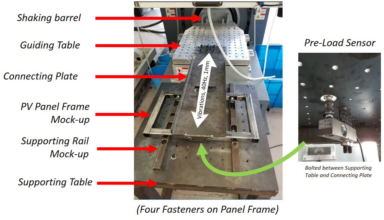
Figure 1: pictures of the experimental test setup used to submit a PV panel frame mock-up fastened onto a supporting rail mock-up with four fasteners of three different kinds (one screwed and two clipped). The vibration is induced transversally by a shaking barrel connected to the Panel assembly via a connecting plate and a guiding table (left picture). The preload pressure on the Panel assembly is continuously monitored via a sensor bolted onto the Panel assembly supporting table (right picture).
We apply sequentially the same methodology to three different fastening solutions (see Figure 2):
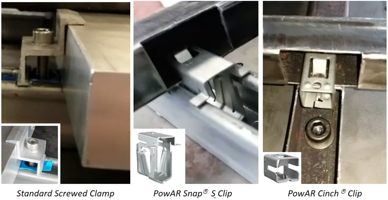
Figure 2: pictures of the three different fastening solutions tested : a standard screwed clamp holding the panel frame from it upper surface (left picture), a clip PowAR Snap S (middle picture) and a clip PowAR Cinch (right picture). Both clips are holding the panel frame from its lower surface.
A standard screwed clamp composed of an aluminum T shaped clamp and a bolt, pressing on the top surface of the PV panel frame. This clamp is a commercial type with a design very popular in the PV industry. The supporting rail design tested is a U shape with an opening of 22 mm. The assembly and the maintenance process require a torque controlled ranch. We use the recommended values here.
A specific product from ARaymond Network, the PowAR Snap S, composed of spring steel clip that fastens directly the bottom surface of the PV panel onto the supporting rail. The supporting rail design tested is a U shape with an opening of 22 mm width. The assembly process does not require any tool. No maintenance is required. The Clip provides as well the electric bonding between the PV panel frame and the rail.
A specific product from ARaymond Network, the PowAR Cinch, composed of spring steel clip that fastens directly the bottom surface of the PV panel onto the supporting rail. The supporting rail design tested has a square section with an opening of 25 mm width. The assembly process does not require any tool. No maintenance is required. The Clip provides as well the electric bonding between the PV panel frame and the rail.
Results and discussion
The results of these three tests (see Figure 3) show a clear difference between the screwed clamp and the two clips tested: with the standard screwed clamp, the preload force starts decaying after 100 cycles (25 seconds) until it reaches its minimum value (PV panel weight) after 3000 cycles (75 seconds). With the two clips tested, the preload force remains stable even after 6000 cycles (150 seconds), demonstrating thereby a factor 6 stability improvement in these test conditions over the screwed clamp tested.
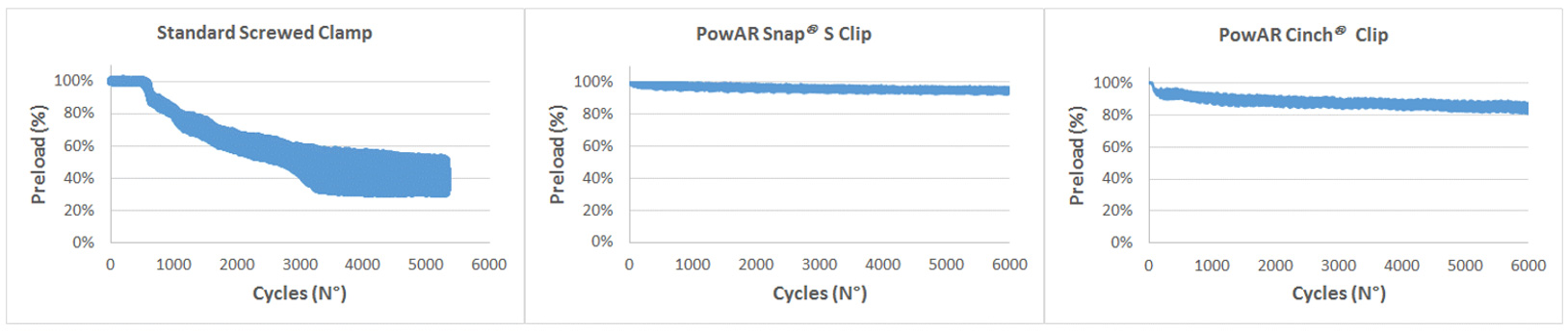
Figure 3: variation of the Preload force with the number of vibration cycles imposed at 40 Hz frequency and 1 mm amplitude in the three cases tested : standard screwed clamp (left graph), PowAR Snap S clip (middle graph) and PowAR Cinch clip (right graph).
The stability of the screwed clamp is poor in these tests and is well known for the technology of threaded fasteners: it can be improved using additional techniques (Loctite, two-nuts, …) but with an impact on assembly time and cost. The preload torque is known to be critical to minimize self-loosening and that is why torque control is mandatory to secure the fastening performance over the lifetime of the installation.
The clips tested here are not threaded fasteners, the preload is obtained via an elastic element that is designed to bend and absorb the vibrations induced displacement over the lifetime of the installation. Therefore, it does not require any maintenance. The test results show that the elastic deformation of the clip is able to maintain a stable fastening of the PV panel, despite the very aggressive conditions provided by the Junker methodology.
Conclusions
We propose an adaptation of the Junker test setup and methodology (DIN 61551) to the specific case of PV panel assembly. We compare with this method a selection three different fastening solutions and demonstrate at least a factor 6 improvement in the stability of the two clips over the screwed clamp tested. We suggest to adopt such a method to improve the stability of the future fastening solutions of the PV installations in order to minimize further the risks of PV panel detachment over the lifetime and to reduce the maintenance assembly costs of these installations.